geo-logaritmica.соm
Introducing DATAMINE Studio 3 / Studio RM

variogram Chapter 1. Intro
titleprefacesample fileslaw of cadlicensingstudio 3 startstudio 3 windowsprofilesdatamine file categoriesdatamine file typesloading external datamine filevisualizerredrawplane by 1 pointworking file directory structureloading autocad fileadding cad file to projectadding dm file to projectlaw of softwareunloading filesproject filessheetsloaded dataexport to autocadbezier's axiompreview dm filesthe bottom line Drillhole Modeling
 String Modeling
 Wireframe Modeling
A man is to suffice his salary rather than salary to suffice the man.
(Georgian Proverb)
 Longitudinal faults
|
 Cross-sectional fault
|
 Terrain isolines ACAD Terrain isolines ACAD |
 Terrain strings DM
 |
 Drillhole Manual
 |
 Drillhole database Drillhole database |
 Datamine 3D Holes
|
 Terrain DTM
 |
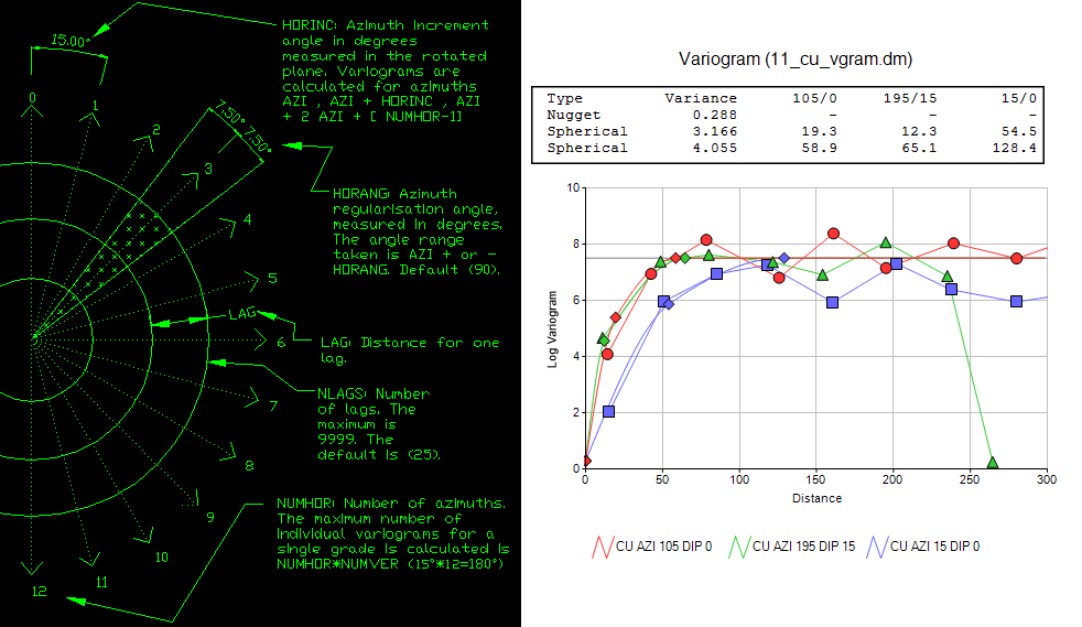
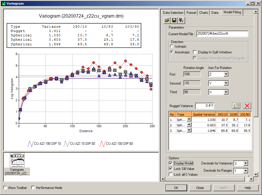
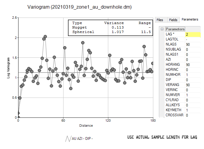
 Variograms
 |
|
 Odixe Strings
 |
 Sulfide Strings
 |
 Ferrari GTO
| |||||
| 1) | If you do something that works, go on with it. |

|
| 2) | If you do something that do does not work, stop doing it. | |
| 3) | If you are not sure what to do, do nothing. |
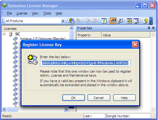
Select the digital key (numbers that you receive from Datamine office in the email text or as TXT file attachment) and copy it to the clipboard.
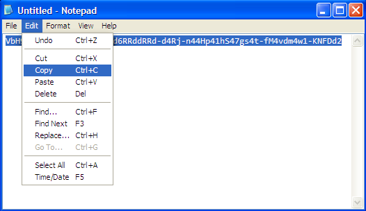
Go to Start | All Programs | Datamine | Licence Services | Licence Manager
Wait for the License Manager to open. Press F1 to bring up the Register New Key dialogue. Most likely you will see the key pasted in the window cell appeared. This happens if your machine clipboard contains the key. If the cell is blank, that is the clipboard is empty, copy the code from Notepad and paste it into the space provided and press OK.
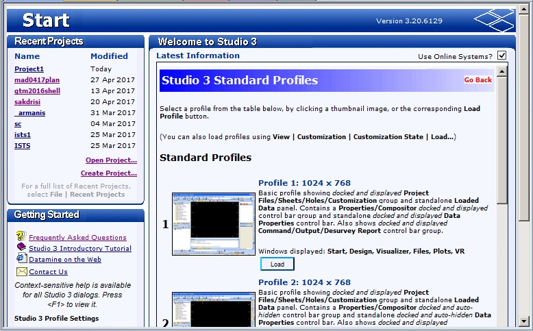
Launch Studio 3 either clicking its icon on your desktop, or choose Start | Programs | Datamine | Studio 3
Select Create Project

to open Studio Project Wizard
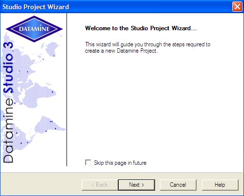
Press Next > to open Project Properties
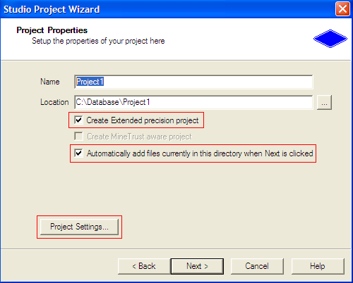
While you pick up a new name for the project in the Name cell, its name changes in the Location box, too, as you type it in the Name cell. Project file name may depend on your mining project name, it can also take your favourate car model or pet's name, etc. You may press Next > with Create Extended precision project ticked off, should you go further with no changes to Project Settings. But for now, just make sure Create Extended precision project and Automatically add files currently in this directory when the Next > is clicked are ticked off and press Project Settings... button to change Project Settings
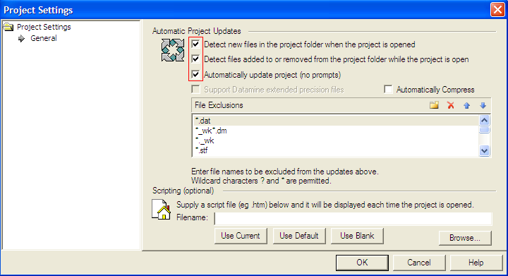
Tick off the boxes as highlighted on screen shot. By doing this you will make sure the files are added to the project automatically. We will discuss later what it means. For now, press O'K to return back to the Project Properties
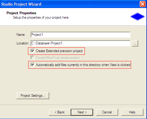
Tick off Create Extended precision project again (it comes out blank after you choose to change Project Settings in previous steps), and press Next >
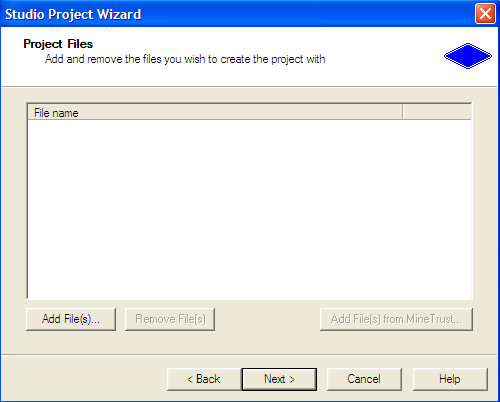
We have no files yet to add to the project in the Project Files window. For this moment, just press Next >
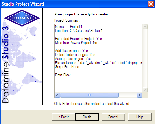
Click Finish
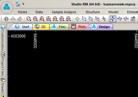
You will see a Design Window. By default it is set with black background.
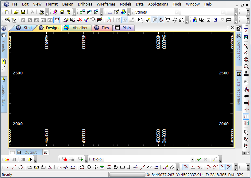
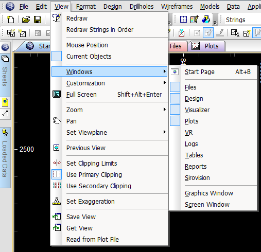
By default, Studio 3 displays the following window tabs: Start, Design, Visualizer, Files, Plots, VR. You can activate a window by pressing on the tab. If you accidentally closed any of the windows or want to display additional windows, go Views | Windows , and select from the menu.
bar
Now press the Start tab. Click either on the Current Profile or Select images in the Getting Started section.
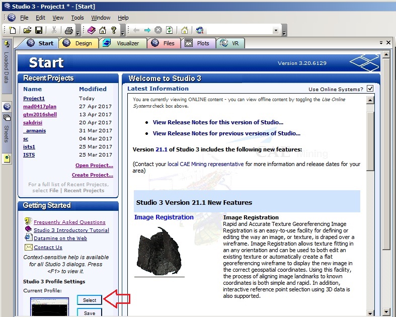
Work environment is called Profile. Profile 1: 1024 x 768 work environment is the default profile is Studio. But you can scroll down and pick up any of the
profiles that you find more comfortable and press on Load button.
In project session, Datamine files are variably devided into 2 categories: internal and external. If a file is added to the project, it is considered internal. Certain manipulations in Studio 3 require files to be added into the project before performing calculations or operations. Any Datamine file which is not added into the project is considered external. Technically there is no difference between the files. One and the same file may be external for one project and internal for the other one.
In this tutorial we will use the following types of Datamine files:
In Studio 3 the term external file
is rerserved for Datamine files. From Studio 3 point of view,
CAD or TXT file being
imported, manipulated, or exported, can not be considered internal or external. If you have not yet downloaded
sample files, go to sample files section to download them, or else
download a single sample file,
a wireframe of a tectonic faults, used in this exercise.
Un-RAR to you hard disk (should be C:\\Downloads)
To import it into Design window as an external file, go to
Instrument panel, Data | Load | External Datamine File | Wireframes
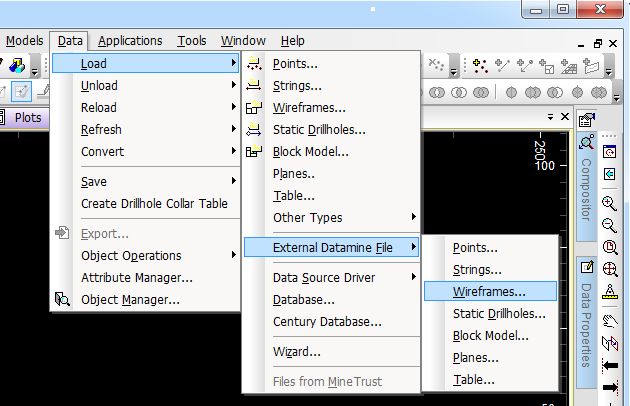
Browse for the file tm_quartz_fault_wfTR.dm on you hard disk, select it and press Open.

In the next window select tm_quartz_fault_wfPT.dm and press Open
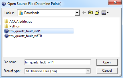
Press OK

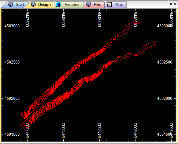
Press OK in the next window. A wireframe file of a tectonic fault will appear in Design window
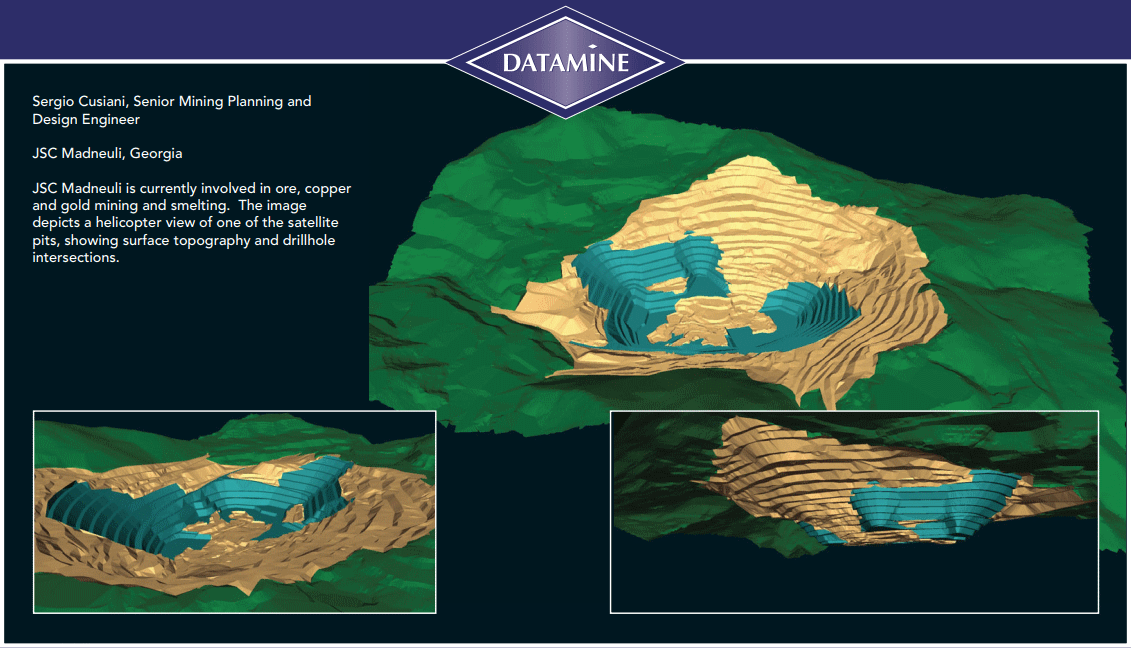
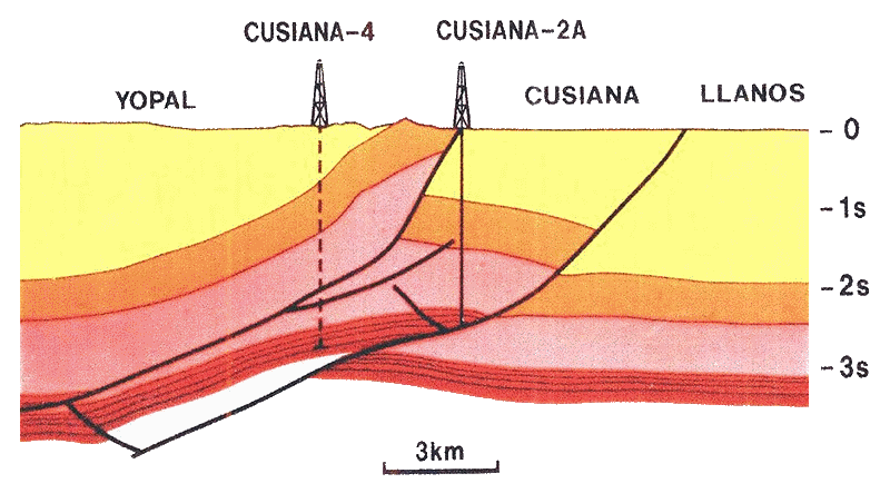
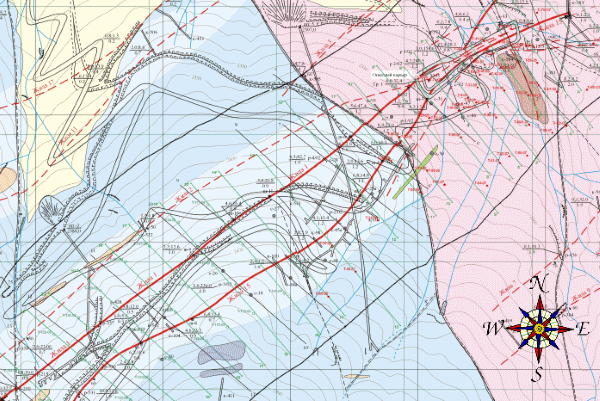
| Once you have Studio 3 installed on your machine, you would already have Datamine official training files available on your hard disk. However in this training course I will be using files I had made while working on a TUXMANNEWK project near Broken Arrow, CUSIANA, CASANARE, COLOMBIA. |
|
Click on the image below to view high resolution vintage map.

IT IS TO BE REGRETTED THAT VISUALISER WINDOW IS OBSOLETE IN STUDIO RM.
In Design window, click anywhere in an empty area of the scene, and type a "screen command" uv, the abbreviation for Update Visualizer, to activate Visualizer window. So called screen commands are further indicated in lowercase letters. You just click in the Design view and type. Other type of commands - command Line commands - are indicated in uppecase letters, though it is not mandatory to type them in uppercase. In this manual when you see a command in uppercase, it means you must enter it into the Command Line.
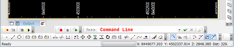
Rightclick on the Visualizer window and pick up the options to change view angle, rotate, perspective, etc.
Users of STUDIO RM can still use the uv (Update Visualizer) key combination in Design Window
         to update current view in 3D Window.
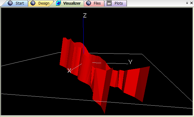
Press Design tab to return to Design Window. Depending on the coordinates of the view point, the file loaded in Design window may not fit into the screen area and not appear immediately. Or when you unload a file, it still might look present on the Design window, though absent in computer memory. In this case type rd to redraw the screen.
Regeneration of the screen is common procedure in CAD systems. Some of them, like AutoCAD, have, if engaged, a function of automatic regeneration of the screen to clean it up from the traces left by removed or unloaded objects. In Datamine Studio 3 you can use manual regeneration only.
You can change view angle interactively right in the Design window by holding Shift key and moving the pointer around with left button on (Shift+Left Button). Remember, you are not rotating the object. You are just moving the view point around.
To return to plan view, type 1 and click on the window anywhere within the empty area and select Plan from the menu. Press OK
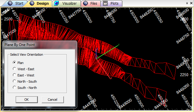
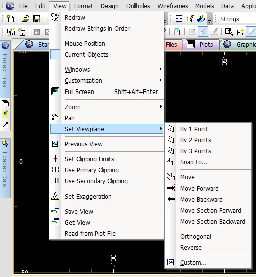
You can change the view plane in Design window by picking up options from the Set Viewplane menu after selecting View | Set Viewplane.
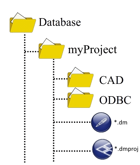
By default, Studio 3 creates Database folder on disk C:, C:\Database. As mentioned above, when creating
a new project, the program also offers you to save it in a Project folder in Database folder. In a project folder
it is recommended
to create CAD folder for supported vector drawing formats (*.dwg, *.dxf, etc.) other than
*.dm, and
ODBC folder for
Excel, Access, text and CSV files. Studio 3 session file *.dmproj and *.dm
files are kept directly
in the project folder.
If you have not yet downloaded
sample files, go to sample files section to download them, or else
download RAR file either by
clicking here or on the picture below.
The file contains digitized isolines of a mine site terrain map. Un-RAR it into C:\Database\Project1\CAD .
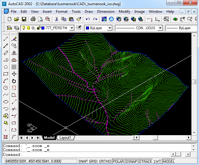
We will add previously downloaded AutoCAD file to the project. It is important to categorize the file
based on the type of objects included in it -- poitns, strings, or wireframes. This time the objects are strings.
It does not matter where the CAD file is located -- in CAD folder of your project, somewhere else on
the hard disk, or on the memory card. By Adding To Project
you create Datamine
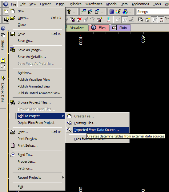
files out of CAD files -- In Design window go to Menu bar > File | Add To Project | Imported From Data Source....
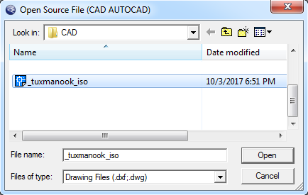
In Import Data window, Driver Category pick CAD, pick AutoCAD(strings) in Data Type. Press OK

In the Open Source File window locate and select the desired file an press Open
In the Read drawing file tick off Load All Layers to view the AutaCAD layers you would want to use. This time we use all of them. Press OK
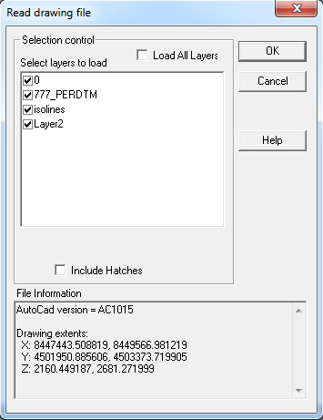
Tick off Table file box and leave Point file and String file boxes intact. If you do not want to keep Autocad file name for your Datamine files, you should enter a new one in Base file name field. Press OK.
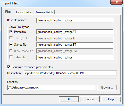
Two new Datamine files are created in your project folder -- string file and point file. They share names with the same root, but different ending -- ST for strings file and PT for points file.
If you have not yet downloaded sample files, go to sample files section to download them, or else download a single sample file, compressed file of digitized isolines in *.dm format. Remember, Datamine creates 2 files of string objects -- point and string file. Unpack the RAR file. Go to Instrument panel, File | Add to Project | Existing files...
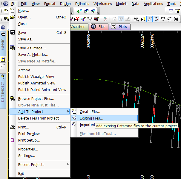
Select _tuxmanook_topoST file and click Open.
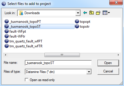
The file will be added to the Project. You can check its availability in the Project Files tab on the left of the Design window.
Computer program makes what we tell it to do, and not what we would like to be done. |
| |
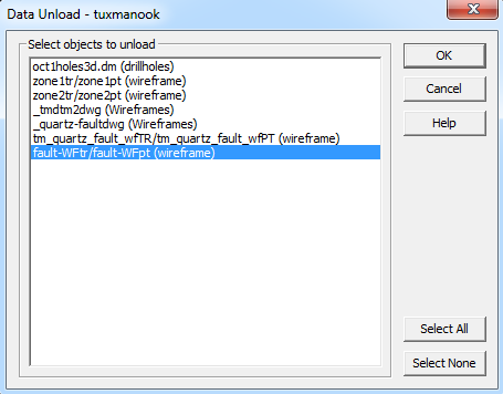
To remove files from Studio 3 session, go to Data | Unload | Select
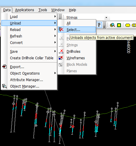
Select file to be unloaded and press OK. The file will be unloaded from the session only,
but will remain in the project files list had it been added there previously .
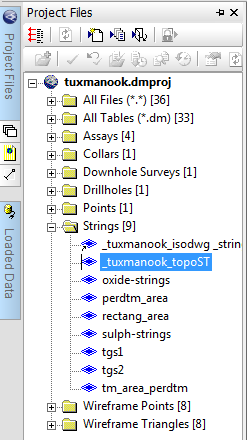
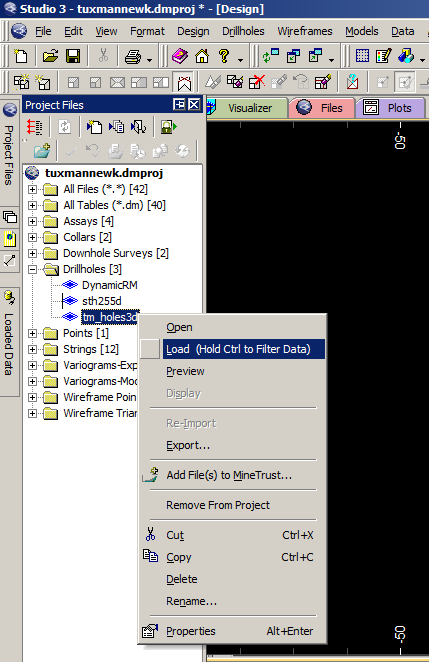
Project Files tab lists all the Datamine files added to the project.

Rightclick a file in the Project Files tab to initiate a context menu and choose one of the options.

You can download a file into Design window by draging and dropping it from the Project Files tab into the window.
Note that if you pick Delete option, the file will be deleted from you hard disk entirely -- that is you will not find it in the Recycle Bin.
Remove From Project option removes the file from current project thus changing the file status from
internal
to external, but the file is retained on your hard disk.
Sheets tab lists files of objects, loaded into the windows. You can hide or display the objects by ticking on or off the boxes. Objects with boxes ticked off will hide from the window, but remain in the session and could be displayed on demand.
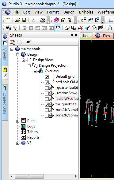
You will need to regenerate your screen by pressing rd to view changes.
Loaded Data tab displays loaded files and attributes they hold.

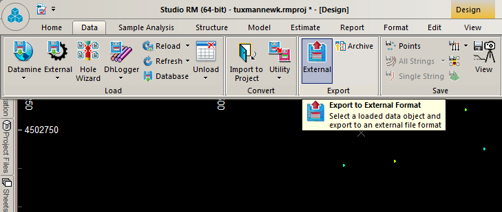
Very often you will need to export Datamine files you created in Studio 3 session into other CAD system to share your work with other individuals or groups which may not necessarily use Studio 3 in their work, such as surveyors, geotechnical or civil engineers, etc. The most popular file exchange format is DWG and DXF (drawing exchange format) by Autodesk. DXF can be imported in any CAD platform.
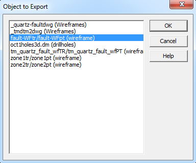
In design window, go to Data | Export

Select the object you created in Design window from the list in the Object to Export window and press O'K
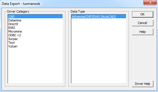
By default, Studio 3 selects CAD in Driver Category, but you can pick up other platforms if needed. Press
O'K.
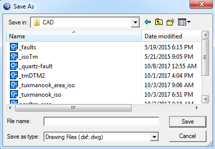
In Save in: box, go to CAD folder in your project directory C:\Database\ProjectName\CAD. Fill in File name: box and press Save.
WHEN YOU SAVE SOMETHING ON YOU COMPUTER HARD DISK, DO NOT FORGET WHERE YOU SAVE IT. |
| |
You can preview Datamine files directly from the Windows Explorer without opening Studio 3 session.
Rightclick the file, choose Preview
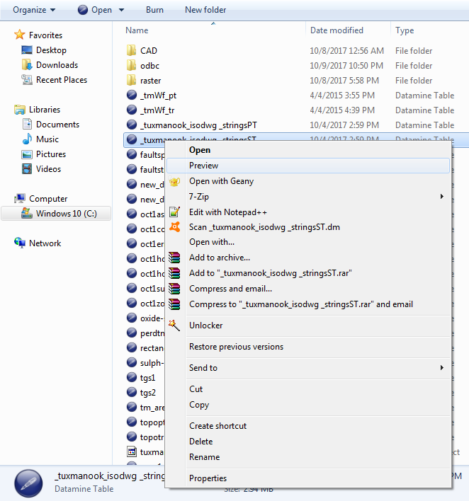
Datamine Table Preview program opens. You can manipulate with the view point by holding left button on and dragging the mouse. Rightclick opens a context menu, where you can choose additional visualisation options. You can not modify or save objects in Table Preview

To master the procedures you learnt, do the following:
Information about the ore body geometry has been obtained from the drillhole data analyses. The sketch below shows what we will be modeling.


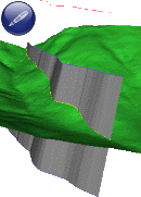
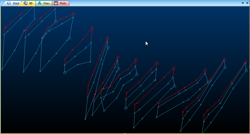
Studio RM offers an advanced automated method of ore body wireframe construction, especially useful for narrow vein wireframe modelling. However it does not give straightforward results and the wireframes need further adjustment, which requires advanced skills. Therefore at this stage the tutorial will go through traditional string modeling, which is applicable for any kind of ore body geometry. On the picture below: an example of the surface automated creation. This is for a demonstration purpose only and CreateVeinSurvace command will not be discussed in this tutorial.

CreateVeinSurface command provides smooth surfaces of hanging and foot walls. With the rotated model functionality (not discussed in this tutorial) one can successfully build a block model within the narrow vein wireframe model no matter the vein thickness. On the picture below the vein is 30 cm thick.

View or download detailed instructions of
creating Excel database for drill hole modelling. Though it is not mandatory to learn them for the moment.
Excel drill hole database file tm_drillholes.xls will be used for creating Datamine drill hole file. You can click on the file name to download it if you did not do it before.
As you can see on the picture below, there are 4 sheels in the file: Collars, Surveys, Assays, Zones.
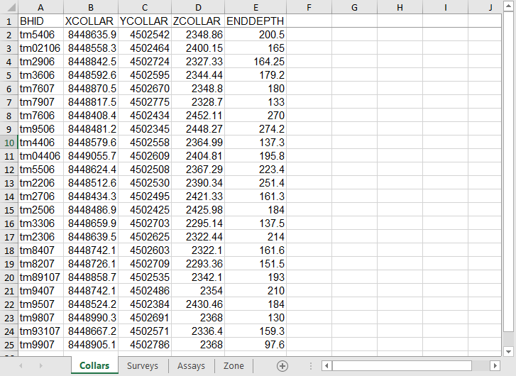
These 4 spreadsheets will be used for creating Datamine drillhole table files. For Collars file, Go to File | Add to Project | Create From Datasource
In the Data Import dialog box, select ODBC as the Driver Category and Tables in Data Type and press OK

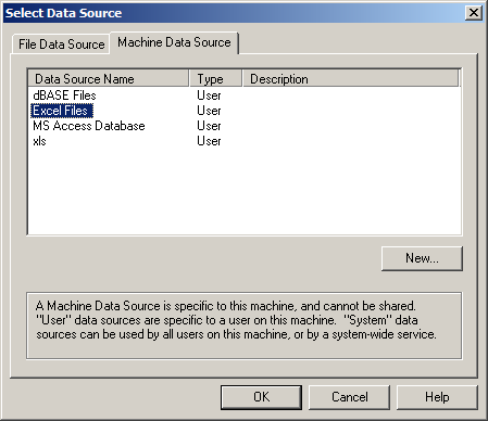
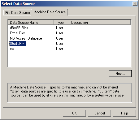
In the Select Data Source dialog box go to Machine Data Source, and select Excel Files and press OK
If the Excel Machine Data Source does not work on you your machine, you will receive a Microsoft warning. With Studio 3, this happens on the minority of the machines and mainly is created by your MS Office configuration. Press New in the Select Data Source dialog and follow instruction of building a new Excel based data source. For more details, go to ODBC Driver Setup For Studio 3 / Studio RM section
In the Select Workbook dialog navigate to the project directory and Excel file location and click tm_drillholes.xls in the Database Name list. Press OK.

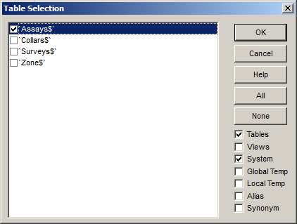
In the Table Selection dialog box make sure the System box is ticked on, then check 'Collars$' box and press OK

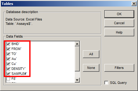
In the Tables dialog box leave all the boxes checked and press OK
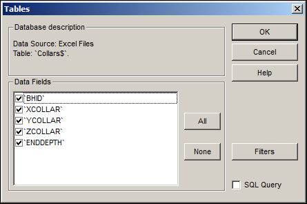
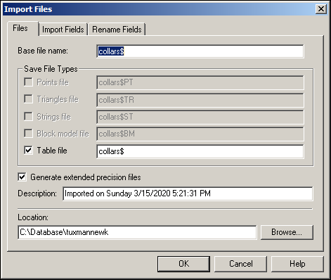
In the Import Files dialog box Datamine creates default name (collars$) with a $ sign at the end as an indication of
a supplementary table file
to the drill hole creation process. You may change the name if you have more than one collar file in the
project, but always retain the dollar sign. At this stage leave everything intact, press OK
Repeat the same steps for creating surveys$, assays$, and zones$ files, but checking corresponding boxes in the Table Selection dialog. In the end you will have 4 supplementary files for creating drill hole file using HOLES3D command.
Wnen working on Assays data, make sure the meaningfull fields are checked on the Tables Dialog, and tick off the check boxes which might accasionally be checked by your system.
You will have four *$.dm files in you Project folder.

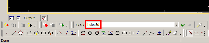
The process is called Desurveying of drillhole data tables (Collars, Surveys, Assays, Zones) to create 3d static drillholes. Use HOLES3D in the Command Line at the bottom of the User Interface: an entry box with white field preceeded with !>>> indicator . The letter case does not matter, you can enter hoLes3D or HoleS3d with the same result, but if you come across with the command in capital letters in this manual or in the Datamine Product Help, it is a convention to type it into the Command Line. (Commands outside the Command Line in the Design Window in texts are written in lowercase). Type HOLES3D and press Enter.
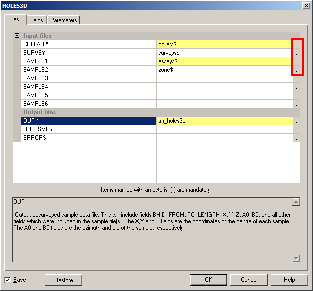
Use selection buttons to the right of the HOLES3D dialog to select corresponting drillhole tables in the Input Files
section and type a drillhole file name in the Output Files section. You can type in a table file name in
HOLESMRY and ERRORS fields and the program will save the info about the data summary and errors if present.
The latter is especially useful for locating either data entry errors, or downhole survey errors and other mistakes in field logging. Press OK.
Congratulations! You have only just created a 3D static drillhole file!

The Project Files list is updated with the drillhole file.

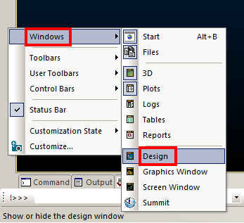
Studio RM is a revolutionary step forward in the Studio series. Thought the developers did not include Design window into the start up configuration, but could not get rid of it because even the Product Help informs you that for some of the operations Design Window is mandatory. It is also easier and faster to work in Design window.

I prefer working in Design Window. Luckily, the developers still allow you to return the Design view back on the UI. But you will have to do it in every new session.
Right-click (R-click) at any spot on the side bar, select Windows > Design.
I hope next generations of Studio RM will have Design window by default
The procedure for creating Datamine table files (*$.dm) in Studio RM differs from Studio 3. Here I will show how to make Collar$.dm file. Also, standard Excel data driver may not be configured for Studio RM, so you will also have to configure the new Excel data source driver.
Go to Main Toolbar, Data | External | Other.

in Data Import dialog box select ODBC in Driver Category and Tables in Data Type as you did for Studio 3.
In the Select Data Source dialog box go to Machine Data Source, and select Excel Files and press OK
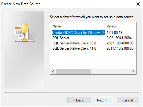
If you get error message:
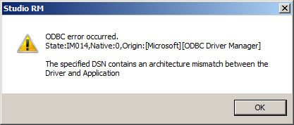
Press OK and close the next dialog. Repeat Data | External | Other, then in the Data Import dialog box select ODBC in Driver Category and Tables in Data Type. Instead of selecting Excel, press New
.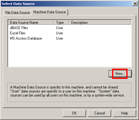
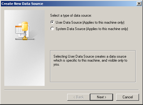
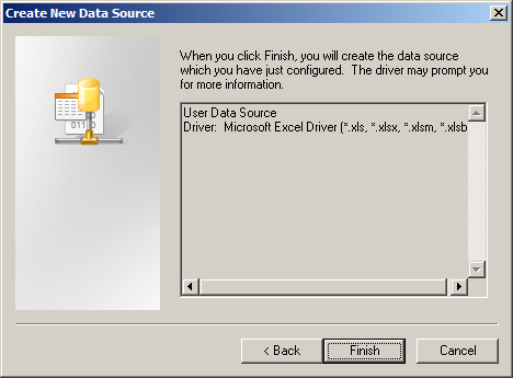
Press Next in the Create New Data Source dialog.
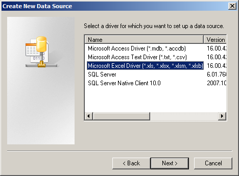
Select Microsoft Excel Driver and click Next.
Click Finish in the following dialog.
Enter any name in the Data Source Name field (for example Studio RM) and press OK.

You will be returned back to the Select Data Source dialog with the updated list of
ODBC drivers. Select StudioRM database driver you've just created, and click here on
Select Workbook. to follow correspoinding instructions.
The rest of the procedures for creating drillhole table files (collars$, surveys$, assays$, zones$) are the same in Studio 3 and Studio RM with one important exception:
Unlike Studio3, Studio RM does not automatically save drillhole table files (*$.dm). These files are kept in the memory untill you turn off the session. Therefore, make sure you save them in your project folder before closing the program.
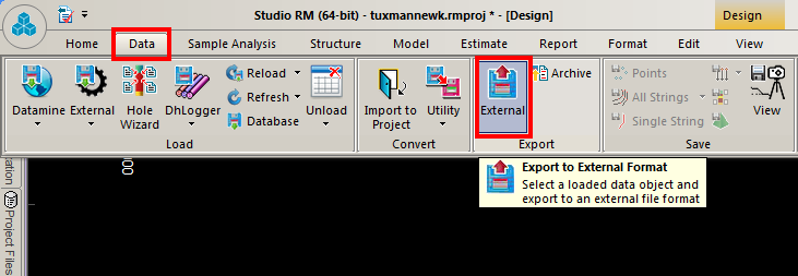
To save collars$.dm, go to Main Toolbar, Data | Export | External
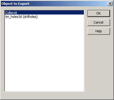
Select Collars$, press OK.
Browse to your project directory and save it as collarsrm$.dm to distinguish the file from the one you created in Studio 3 session (if you use both programs). Press OK.

Go back to Main Toolbar and create surveys$, assays$, and zones$ files and save them to the project. Refer to Desurveying Drill Holes section of this manual to create 3d drillholes in Studio RM with HOLES3D command.
Create New Data Source tab has no Microsoft Excel Driver selection option if you have MS Office 2010 installed on your machine. Contact Datamine support office, or upgrade to MS Office 2016 or higher.
Drillholes made with desurveying process are called Static. Another type of Datamine drillholes is Dynamic. You do static holes first, then dynamic holes out of static ones (if needed). But before I show you the procedure, you should understand the difference. To my opinion, the necessity of dynamic holes depends on the accuracy of downhole survey in the field.
Many experienced Datamine users, even those self-decorated with notorious AusIMM note at the bottom of every e-mail, may not know what is static hole and what is dynamic. I’ve met with the one in 2008. 10 years later he still did not know what I was talking about.
Dynamic drillholes inhabit only the Design Window current session. You can not find them in the Project File or in the Files Window. But you can rebuild static drillholes which inherit properties of dynamic drillholes.
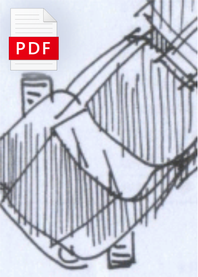
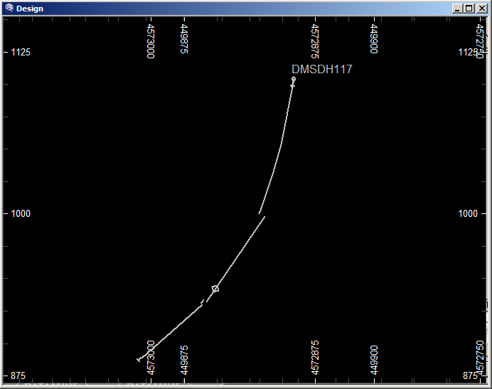
Drillhole trace is not a straight line. Rather, it is a compound curve because drill bit penetrates layers with different physical characteristics, which coupled with drill rod rotation efforts make the drill bit diverge from the straight line. When a field surveyor makes a downhole survey of the drill bit penetration into the ground, he writes down sample intervals dip angle and dip direction. Studio 3/RM algorithm of HOLES3D command calculates location of midpoints and builds 3d drillholes and locates them on the imaginary drillhole curve. Since the sample interval is a straight line, placing the centre point on the curve of the trace automatically means end points are out. But how much should they be out? If the downhole survey is both accurate and precize, you do not need to worry about it as much as the gap between sample ends is not noticeable. But downhole survey equipment and human errors in the field can do a significant impact on the issue making the drilhole samples look like the ones I draw or even worse! Probably this is the point of Datamine dynamic holes process when static holes are re-surveyed to make sample end points meet to the detriment of the sample centre points having been distanced from the hole trace. Both types of drillholes can be used for ore body modelling and estimation. Probably, dynamic holes have some reserved functions for development in future.

Opposite to dynamic, static drillhole centre points lay on the drillhole trace. Correspondingly, sample interval end points are out of the trace line.
...You will need table files you created for HOLE3D process downloaded into the session. Go to Project Files, select files by pressing and
holding CTRL button and clicking on the *.$ table files. Then release CTRL, R-click and choose Load.
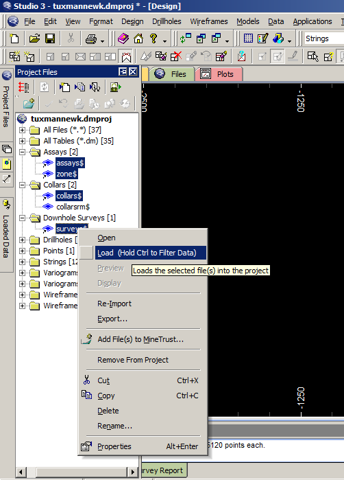
You will note collar points on the screen. Next, go to Main Toolbar, Tools | Define Holes

In the Define Hole Tables dialog select table files as on the picture below, press OK.

Dynamic holes dwell in the Design Window only, not even in the session memory. They are not saved on the hard disk and will dissapear
after the session restarting. The only way to save them is Rebuilding Static Holes From Dynamic Holes.
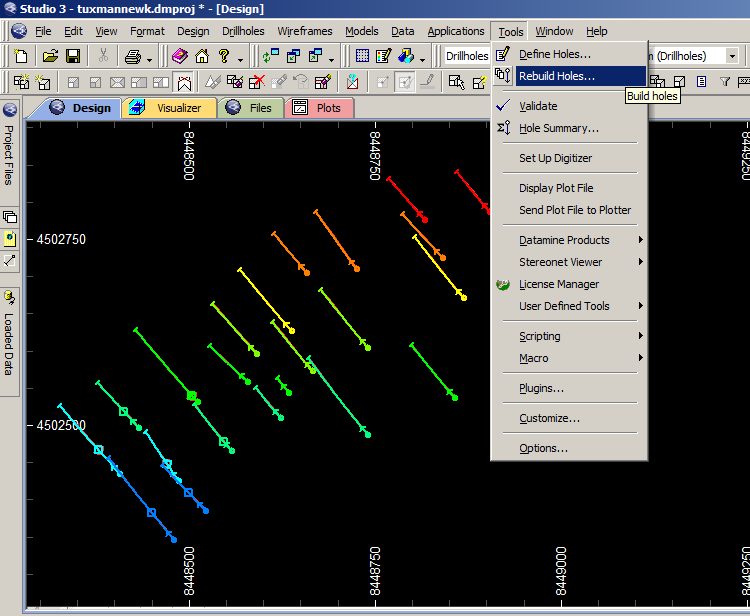
Go to Tools | Rebuild Holes...
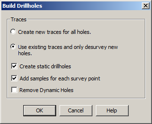
Build Holes dialog appears. Makes sure the Use existing traces and only desurvey new holes radio button is ticked on.
Check the Create static drillholes box. Press OK
A new Static drillhole hole file is created and Datamine gives it a machine name. To save the file on the hard disk, go to Data | Save | Static Drillholes. Select the new static file an rename it if you want.

Navigate to the project folder and press Save.

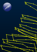
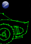
I've come across with a lot of examples, when dynamic hole process is the only remedy. This happens if you import drillholes made in Micromine. Micromine is 2.5D software while Datamine is true 3D! As usual, you do not have access to the raw database to make drillholes from scratch because those who gave you a crumpled Micromine file will make sure you do not have the database available. Another issue might have been the downlole survey performed not accurately enough. In both cases use dynamic drillhole modelling.
Below is the picture of the same drillhole cured by the dynamic process. The effect is obvious, though not perfect. This is maximum you can do with fabricated Micromine drillhole file. If you have access to the drillhole database, you can be more specific: it might happened to be the downhole survey or/and records issue. If so, you have explanation to your HOLES3D drillhole geometry on the picture above, and the dynamic process effect on the static drillhole on the picture below. You are the only manager of your project and must be able to answer questions.

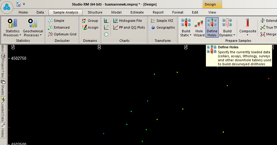
Studio RM users can load *rm$.dm table files into Design Window, then go to Sample Analysis | Prepare Samples | Define Holes
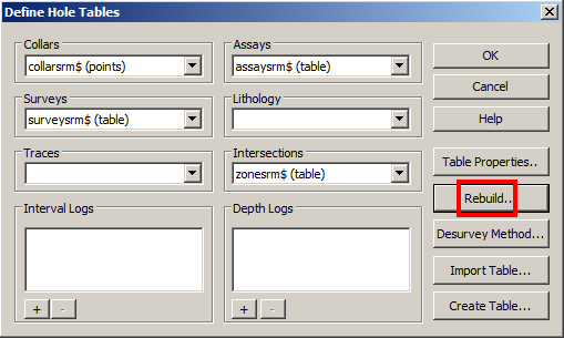
Pick corresponding table files for each entry box, click Rebuild.
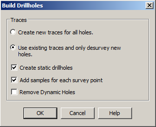
Follow check box pick-ups on the picture below, press OK.
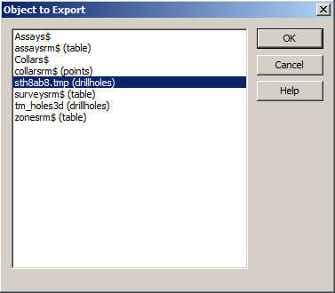
A new dynamically treated static drillhole is created in the Datamine session. To save it on you machine, go to Data | Export | External
Pick the sth*.tmp(drillholes) machine generated file and press OK.
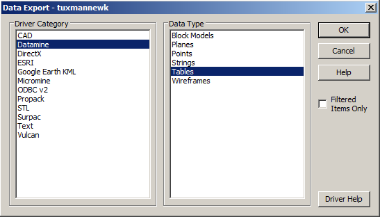
In Data Export dialog select Datamine Driver Category and Tables in Data Type fileds. Press OK.
In Dynamic Data Table dialog navigate to the project folder, change the file name and press OK.

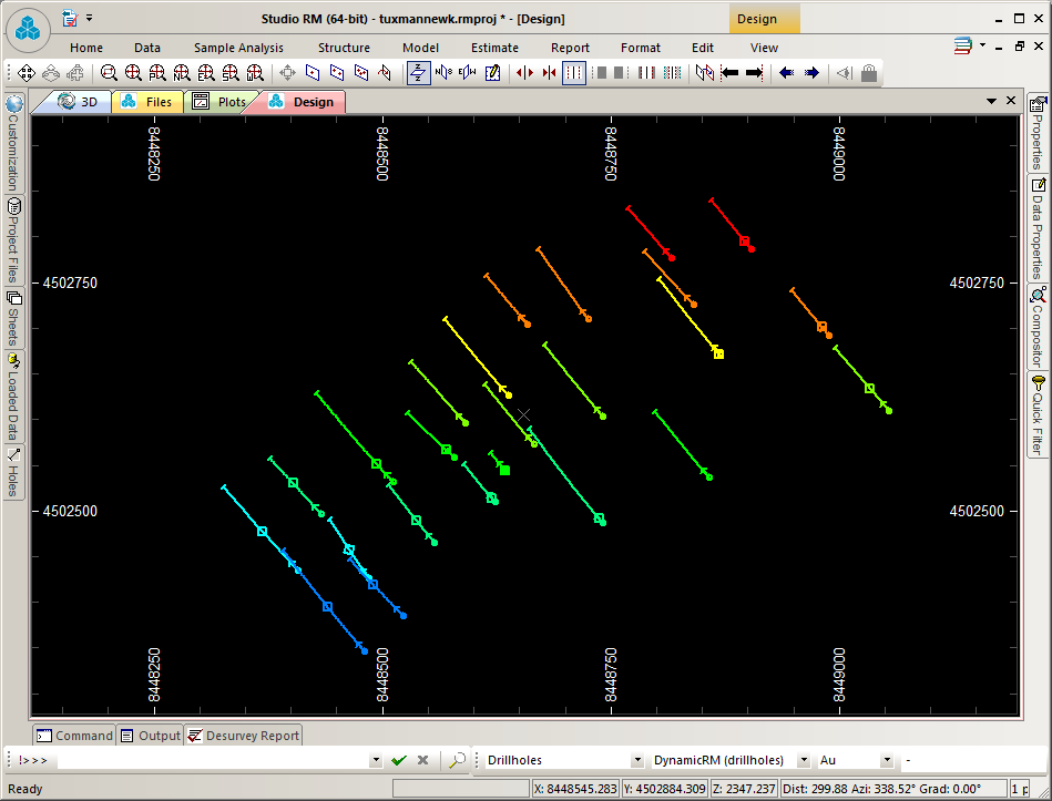
Load the tm_holes3d.dm drillhole file in the Design window, if you did not do it before. Project Files > Drillholes, R-click the file name and select Load from the menu.
Press Zoom Extents button to bring all the drillholes into the view.

The drillholes are coloured by the program with random colours. The colours are meaningless. But we can add values to any colour by assigning it to a range of drillhole value, be it grade or mineralization zone.
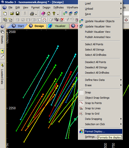
R-click in the view, select Format Display from the menu.
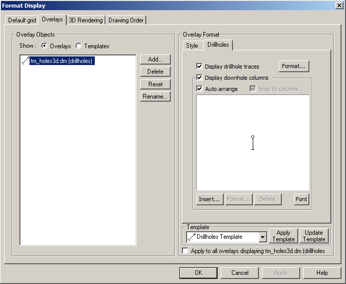
In Format Display dialog box, Overlay Format > Drillholes tab, pressFormat... button.
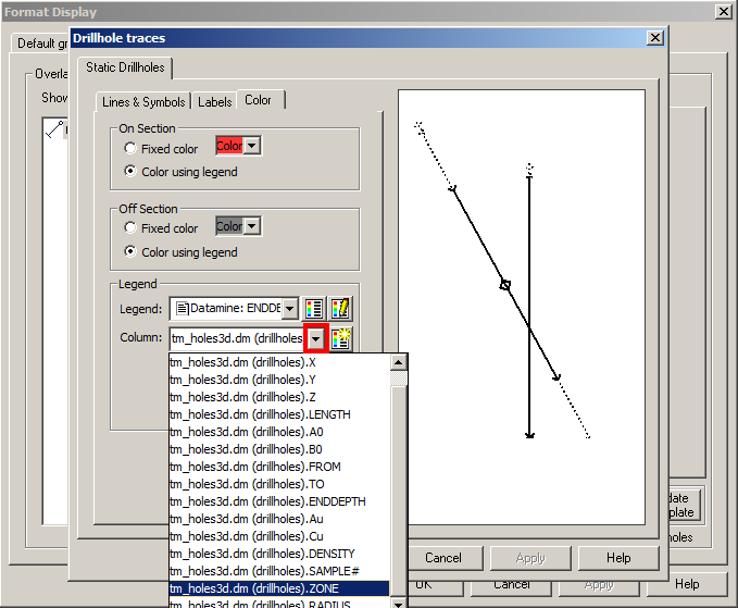
In Drillhole Tracesdialog, go to Color: tab, press the selection button to the right of the Column field in Legend group. Select ZONE from the drop-down menu.
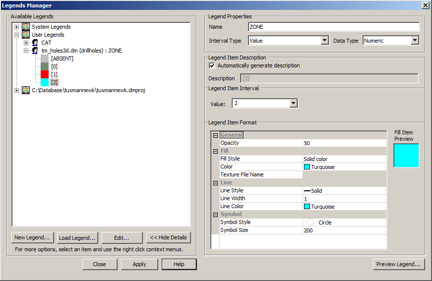
To create a legend for ZONE, press the Edit Legend button in Legend group.

Legends Manager > click New Legend... button.
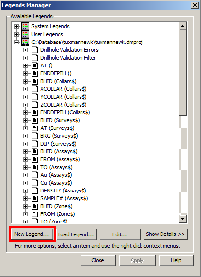
Select Use Object Field radio button and delect ZONE from the Field drop-down menu. Press Next.

Select Use Legend Storage radio button and click Next>.

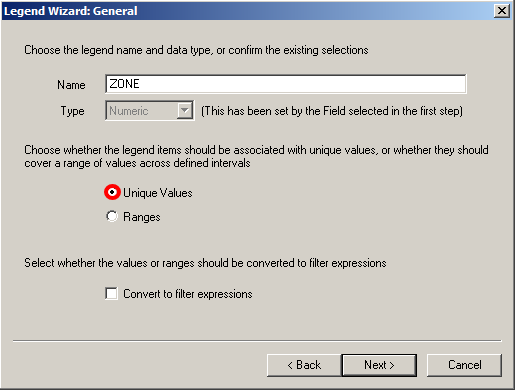
Click in the Name field and leave just the ZONE wording. You do not need long names because they would not fit entirely into dialog name boxes. Use name as short as possible. Select Unique Values radio button, click Next> button.
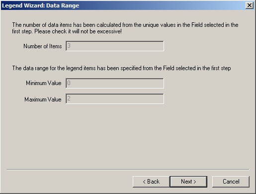
Click Next> button in the Data Range dialog.
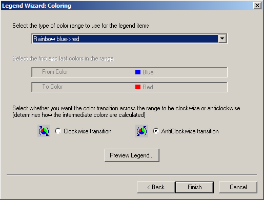
In the Coloring dialog click Finish.
In the legend Manager window you can pisk up colours for zones. In this case red for oxide zone (ZONE1) and turquoise for sulfide (ZONE2). Press Apply button, then Close button.
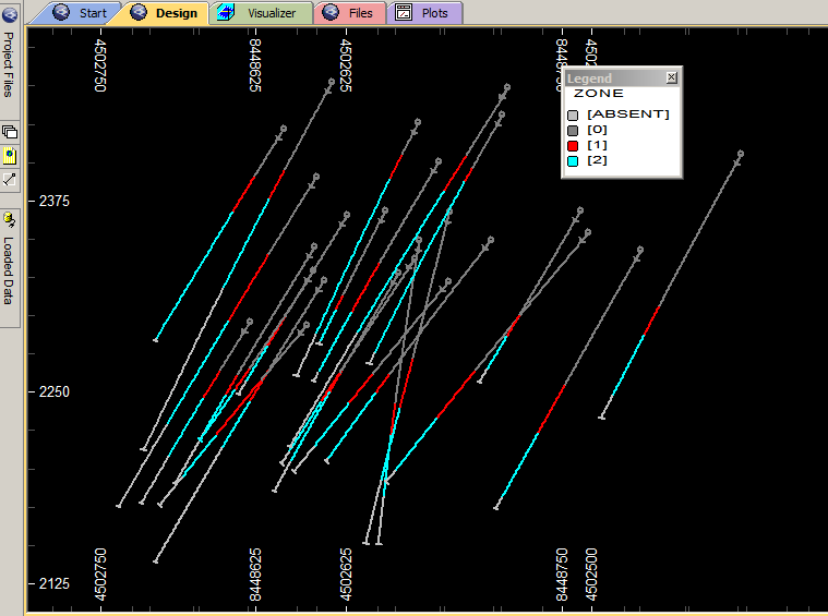
You are back to Drillhole Traces dialog, but this time with the user legend you've just creatred, in the Legend: box. Note a human head profile in front of the legend name -- it is an indicator of the user legend storage at C:\Users\YourName\AppdData\Roaming\Datamine\Legends.
Press on Show Legend button next to the Legend: selection box to display the colour palette in the Design window.
Press Apply button, then OK.

In the Format Display dialog, press again Apply button, OK.
You will need a site DTM, tectonic faults wireframes and the Datamine drillhole file you made previously. You can use the drillhole file supplied, if you like. If you have not downloaded the sample wirframe files before, use the download links below.
-
Wireframe of longitudinal tectonic faults, Datamine file.
-
Datamine 3D holes.
-
Terrain DTM, AutoCAD file.
Un-RAR the files. Do not forget to place the DWG file into the CAD folder, and place the Datamine files in the project folder.
In Chapter 1 you learnt how to load files, DM or DWG, into the Studio 3 Design Window. Once the files are loaded, type uv to update the Visualizer Window with the new objects. R-click and use the context menu to pan or zoom. Press and drag the mouse wheel to rotate around the view. Studio RM users can switch between Design and 3D Windows typing uv in Design Window and rvr in 3d Window to redraw 3d view into Design Window. The rvr also opens Design Window if it was closed.
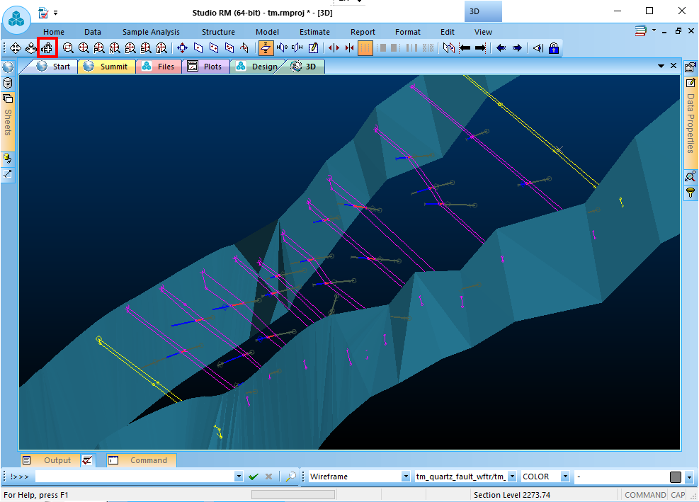
Click on the Design window label to return to design view.Regardless the current view plane orientation, you can can always
set the top view by pressing

Type twsl which is an abbreviation for toggle wireframe slice, then type rd to redraw the screen.
Your screen view might be different. It depends on the view plane elevation, which can be controlled by Move Plane Forward and Move Plane Backwards buttons on the right sidebar.

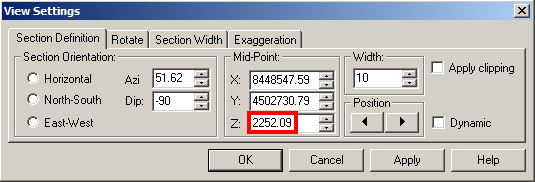
You can also control the view plane elevation by Z: entry box in View Settings dialog box, which can be engaged by pressing View Settings button on top of the side bar.
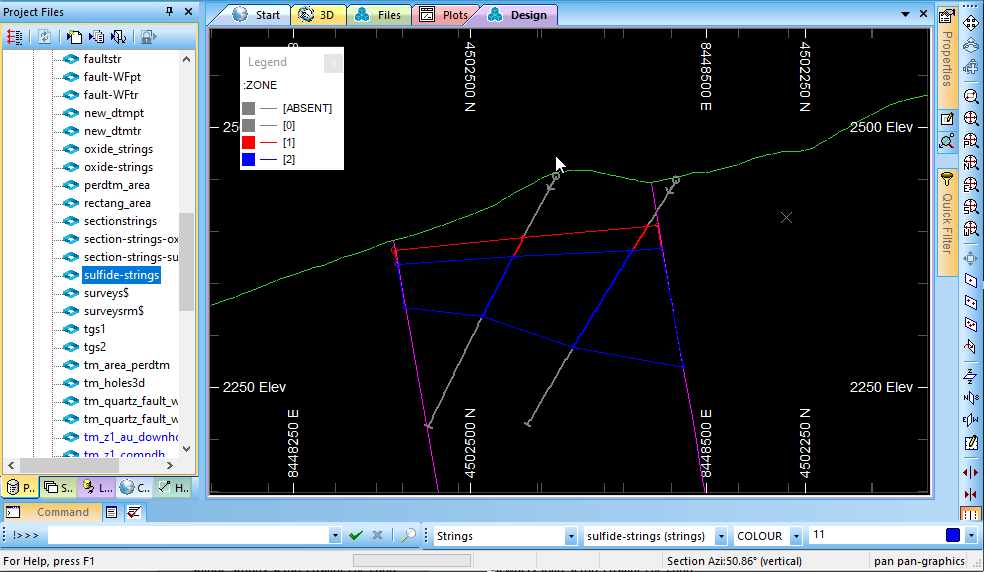
Press the 2 key on the keyboard, target along the apparent continuation of any drill hole row, click and hold the mouse button on the screen to the left then drag the cursor to the right as if you want to slice along the row. A rubber line follows the cursor. Release the mouse button. In the Select View Orientation group select the Vertical Section radio button, press O'K
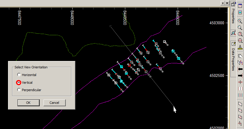
A vertical section is displayed. Though all the drillholes are apparent and pile up to create a mess. What we want is to turn off the drillholes that do not position on the vertical plane we created. This is done through the View Settings dialog box by pressing View Settings button on top of the side bar.

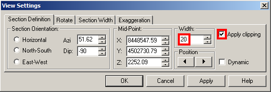
In the View Settings dialog box set Width: to 20, and tick on the Apply Clipping check box. Click O'K. 20 metres is the clipping width. It means that the objects (drillholes) or even patts of the object located within the width, will be the only visible on the screen. You should always try different width values to adjust visibility of objects per your task requests
Vertical section view after clipping applied:

Next, you will be drawing strings in vertical planes through all the drillhole rows starting from the left corner. But before that, press 1 key to get the plan view.

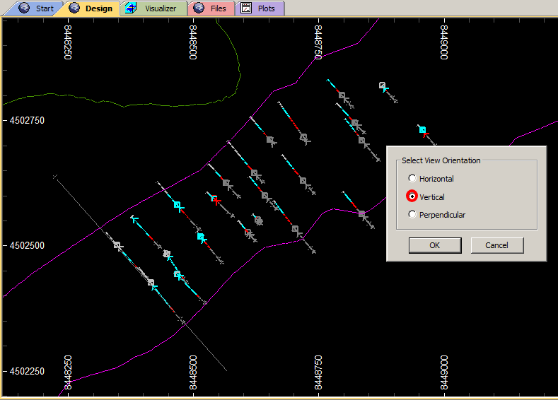
Press 2 and click on the screen as if you want to slice the view along the first raw of drillholes on the left side. The rubber line following the cursor will help your position the second point. Click the mouse button, then select Vertical radio button to get vertical section view.
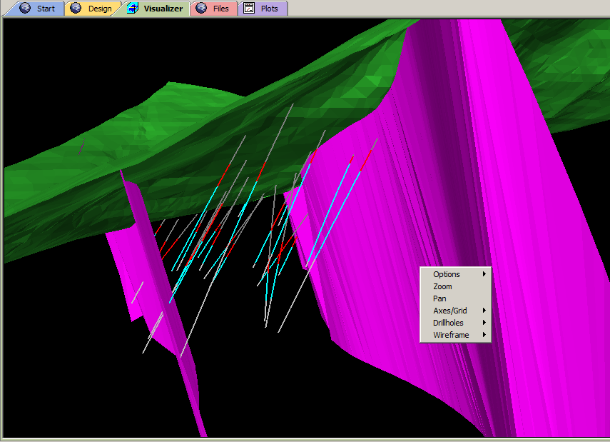
It seems the Turqouise colour we picked up for the sulfide area is not standing out enough against the light gray colour of the absent grades. Probably it would be better to change the colour in the palette. R-click on the view, Select Format Dispay...>Drillholes>Format... . In Drillhole Traces dialog menu press Color tab. Press Edit Legend button.

Change the the colour of the [2] palette item to blue and press Apply. Then pres OK in the following, and Apply in the next dialog to close formating.

Type ns on the keyboard for new string. A colour palette apears at the bottom of the view, from where you can select the colour for the string. Pick the red (#19) colour.

Draw a string as on the picture below. Use left button when drawing at the tectonic faults and right button for exact positioning of the string point at the oxide zone top and pottom points. Remember, when string command active, right mouse button is used for exact snapping of the string points. If you use left mouse button, the point is placed on the view plane. Use Zoom In and Zoom Out buttons while drawing the string. The ns command remains active until you press Cancel button at the top right corner of the view port. Also, use right button to position the last point of the string with the first one. Or else, do even better -- type a screen command ipo (discussed next) to automatically close the countour string. Note, that the string is yellow, which is the default colour for selected objects. Therefore, never use yellow colour for objects, otherwise you will be misguided.
Warning!!! Use left button if you do not need exact positioning. Do not use right button click at the tectonic fault wireframes.
If you do, your string point will randomly snap agaist the closest wireframe triangle point, which can
be way out of your drawing plane.

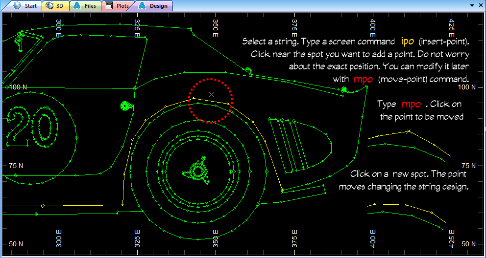
A few string operation commands will be useful for your drafting techniques. You may missed clicking on the drillhole sample interval point. Or need to delete extra points you created while clicking around acidentally. With the string selected, type a screen command:
ipo: (insert-point) to insert extra point on the string.
mpo: (move-point) to move the point to a new position.
dpo: (delete-points) to delete a string point.
clo: (close-string): to add a string segment between the first and the last point, thus closing the string. You can use this command to close the string while drawing any of the contour strings in this tutorial, or select the string and apply the command to make a closed countour. This command will be useful for checking if the strings are ready for wireframe modelling.
If needed, use RMB to snap the manipulated points precisely on the existing points.
HOW TO DIGITIZE BLUEPRINTS WILL BE DISCUSSED AT THE END OF THE TUTORIAL.
Finally, you need to save the string into a file. With the string selected, press Save Current Object button on the Main Toolbar.

Press Extended Precision Datamine (.dm) file in the Save New 3D Object dialog.

Navigate to project folder and enter oxide_strings in the file name box. Press Save button.

Always keep an eye on the object type and active object name box in the Main toolbar. All the cross sectional strings of the oxide zone must be saved in one, oxide_strings.dm, file. If you create new strings by accident while working with oxide_strings.dm, all the newly drawn strings will belong to the new string object. Seemingly, if you have more than one string object file, accidentally it may become active so that strings you draw will be saved in the very current object, which could not necessarily be the one you want to update. Therefore, always pay attention to the current object.

From now on the program session and screen shots will entirely be done in Studio RM.
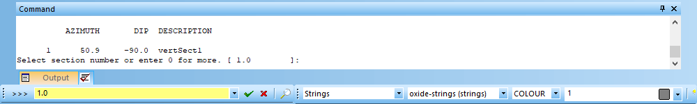
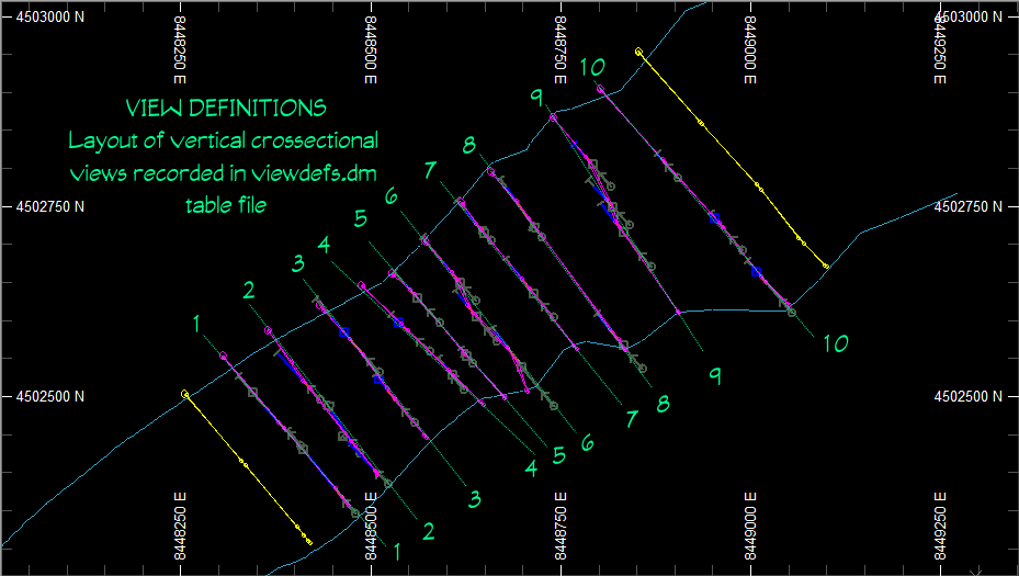
sviTyping svi (Save View) brigs up a view saving option. Change the name of the view to more suitable one (vertSect1). We will go back to vertSect1 view when drawing strings for sulfide ore body.
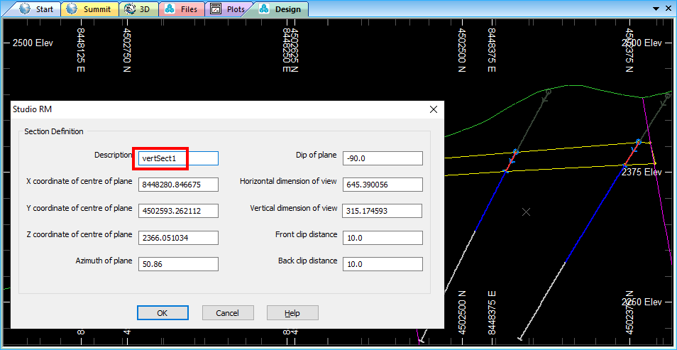
Type gvi (Get View) to revert to numbered view by typing the view number into the Command line and pressing Enter
It is important to save view definitions! Press CTRL+S to bring up file save menu:
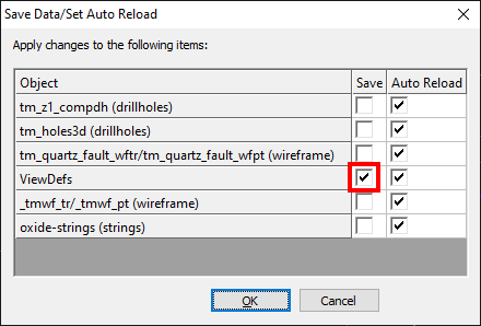
Press OK.
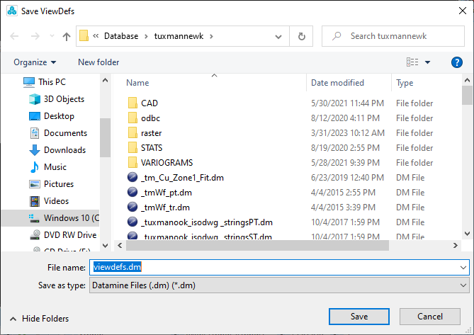
Now your section view definitions (not drawings!) are saved in a file within your project folder.
You can keep the file for other session of Studio, or even give it to someone else to do his part
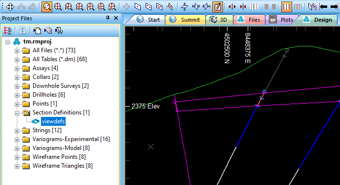
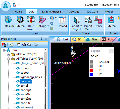
of the task on the current project. In the Project Files docker on the left side of the Studio window the saved viewdefs.dm
file appears in the Section Definitions folder.
Press 1 and click in the middle of the vertical section drawing between the fault lines to get horizontal section view.
The place you click on matters as long as the click point XY coordinates are
used to center the horizontal view on the display while the plane itself is cut on Z coordinate level.
Press 2
and make a section line through the second raw of drill holes to get vertical view of the section. Do not forget to save the view with typing svi.
Use clipping by typing uc if needed. Make sure oxide-strings.dm
object is active. Draw contour lines, CTRL+S to save string and view definition file.
Go on with other rows of drillholes. You should have 10 vertical sections in a row, which means 10 lines in
viewdefs.dm file. Oxide ore body strings with
one of the cross-sectional strings selected will look like this:
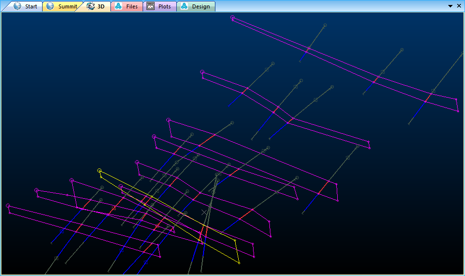
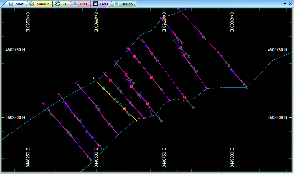
Plan view of drillholes, section strings and tectonic wireframes in Design Vindow.
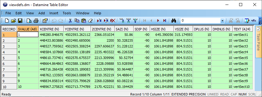
You can view the contents of Section Definition file by double-clicking on the viewdefs.dm file either in the Prject Files docker in Studio session or in Windows Explorer or other file manager from your disk. The file opens in Datamine Table Editor.
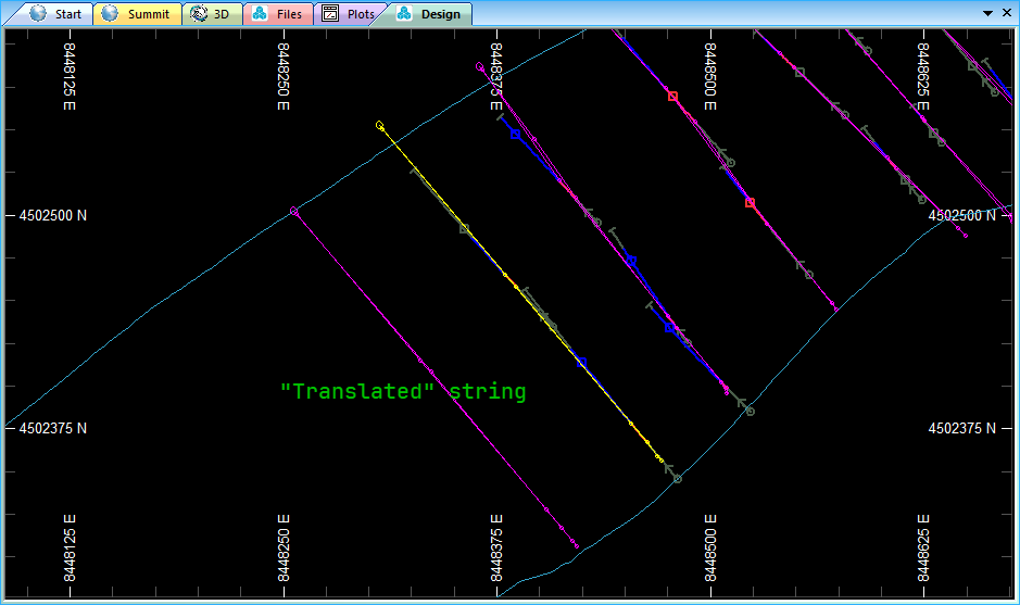
We draw crossectional strings through the drillhole planes to build a 3d wireframe of an ore body. The ore body must be extended at both ends. Rule of thumb is to extend the ore body by at least half of the average distance between the section strings. We need to copy end strings aside by the distance using tra screen command (disscussed below).
In Design window, press on the Zoom Window button and select the right end string area to zoom in.
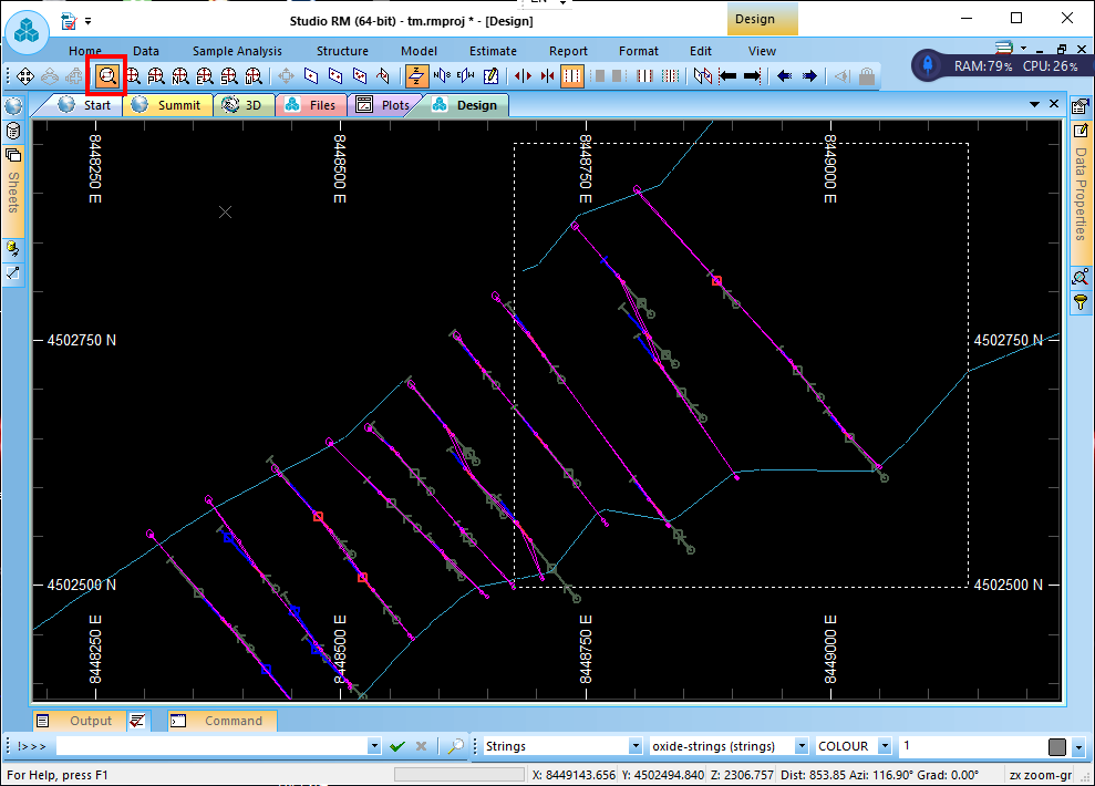
We need to measure the distance between the strings. Type ql, select the first point and then second point followed by a rubber line. Unless specified as RMB (right-mouse-buttone), selecting point always means with LMB (left-mouse-button).
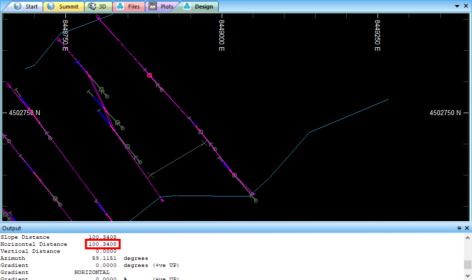
An Output docker appears at the bottom of the inteface, if not previously pinned down. Unpinning dockers lets you save working space while they show up as soon as they are called. Read the data. We do not need exact measurements so that 100 metres will suit. For extending the ore body carcass at both ends, we will use tra (translate-string) screen command. First select the string (it turns yellow), then type tra
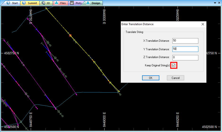
In the Enter Translation Distance dialogue, enter in X and Y cells as specified on the screenshot above. Make sure Keep Original String(s) box is ticked-on! Press OK.
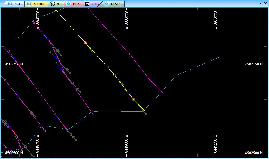
One more string appears to the right of the selected string.
Move to opposite end of the ore body and do the same with the left end string.
X Translate Distance: -50; Y Translate Distance: -50.
Scroll mouse wheel in Design Window to Zoom out and view all objects. We have two more strings at both ends of the ore body carcass.
Type screen command uv (update-visualizer) to view objects in 3D window.
You are in 3d window. Remember one important thing! Almost all modern 3D graphics software, including Datamine Studio (in Design Window!)
use mouse wheel scroll for zooming in or out and
pressing and holding it as middle-mouse-button to orbit or pan. This is very handy and users are so accustommed to this simple
motor function
(there is no need to distract your valuable attention from the working screen to have been clicking on the toolbar button or pressing on key combinations a thousand times per session)
that they use it for racing around the space of their model
as if they are born at the steering wheel of Formula 1 supercar to impress innocent company bosses and shareholders at the presentation with their
brilliant juggling technique in Datamine.

DO IT SOMEWHERE ELSE, EXCEPT FOR DATAMINE STUDIO 3D WINDOW!!!

Interstellar scale effect of using brilliant computing techniques in 3D window
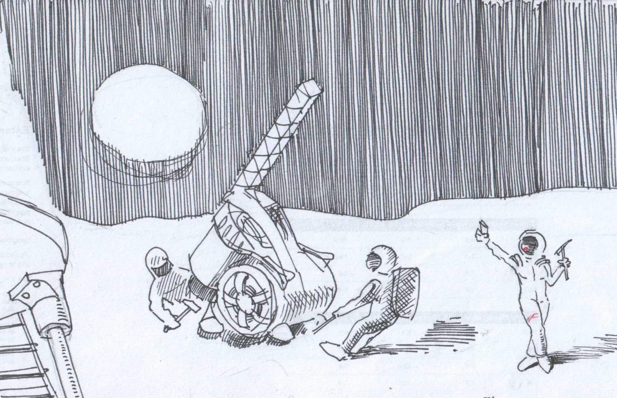
 While in 3D window of DATAMINE Studio RM, with a mouse wheel you can easily scroll yourself out of
                    the window to be lost elsewhere in space at a distance of lunar orbit and unable to spot the location where your space mouse was launched from.
DO NOT USE MOUSE WHEEL FOR ZOOMING IN 3D WINDOW! BY SCROLLING THE WHEEL YOU ARE NOT ZOOMING LIKE YOU DO WITH MAGNIFYING GLASS,
YOU JUST CHANGE THE DISTANCE BETWEEN YOURSELF AND THE OBJECTS, LIKE SITTING IN A SPACECRAFT AND WATCHING
THE EARTH GETTING SMALLER AS YOU TRAVEL TO THE MOON, AND THE MOON APPARENTLY GETTING LARGER AS YOU APPROACH IT.
BUT IN 3D WINDOW YOU ARE IN FACT TRACKING CAMERA AND YOUR PICTUIRE BECOMES OUTCENTERED
AND DISTORTED FOR OTHER VIEW ANGLES. FURTHER MANIMULATION WITH MOUSE WHEEL IN THE ATTEMPT TO GET BACK TO THE INITIAL POSITION WILL OCCASIONALLY SCROLL THE SCENE
OUT OF YOUR EYE REACH.

DATAMINE STUDIO HAS NOT YET PUBLISHED ANY FUNCTION FOR RESTORING A DEFAULT FIEW POINT.
In 3D window activate dynamic Zoom button located between Pan and Spin buttons ot the toolbar. While activated, hold and drag in 3D widnow: up to zoom-in or down to zoom-out. You stay on the same viewpoint, but the objects apparently change their size the same way when you use a magnifying glass.

Use Spin View button to orbit in 3D
CTRL+S, in Save Data dialoque make sure oxide-strings.dm check box is ticked on and press OK.
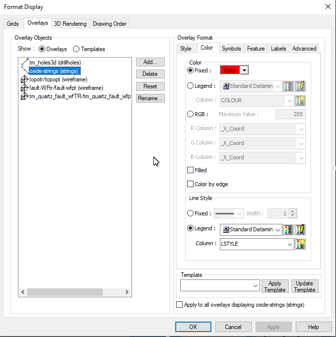
Before continuing with sulfide strings, you may want to know how to change string object colour on the display. You do not
need to select the object. Click with RMB anywhere on the screen, chose Format Display. In Overlays tab, Overlay Objects, tick on Overalys
radio button, click on oxide-strings (strings) line.
In Overlays Format section click on Colour tab, click on Fixed radio button and pick up red.
You will start drawing oxide strings with the Vew #1 you saved previously. Type a screen command gvi and type 1 in command prompt to get the view from the list of views. If for some reason you can't access the viewdefs.dm file, make sure it is loaded into the scene. Find in in the All Tables tab of the Project Files docker on the left of the screen, drag-and-drop it into the scene.
Until now, oxide strings were the only string object on the scene so we were not to worry about what string object is indicated in the objects box on the Status Bar. Any string you draw will atomatically be added to the active strings object, this time it is oxide strings. Use ns command (for new string) to draw a closed string picking up sulfide interval points. Use RMB to snap exactly on the interval points.
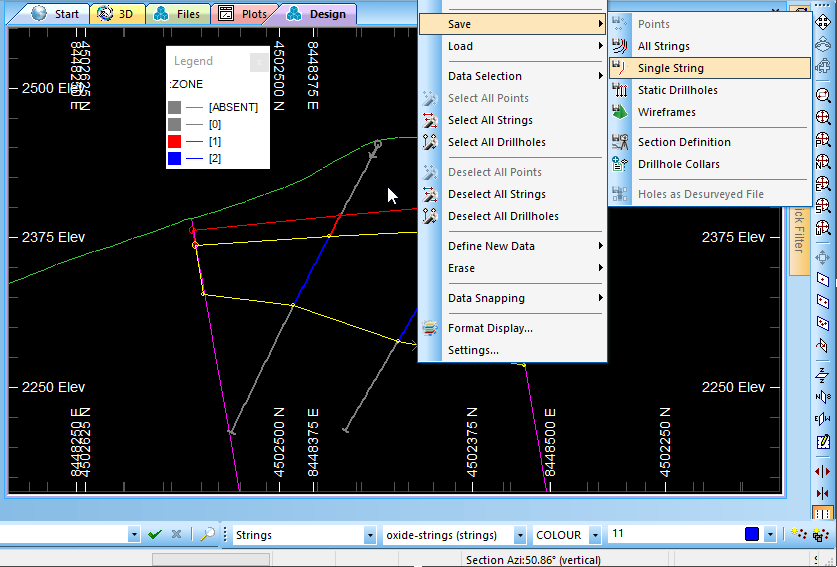
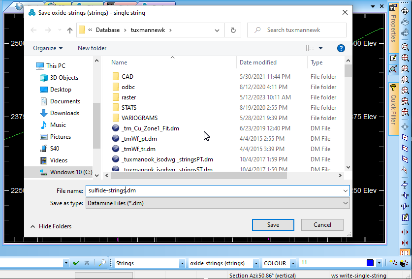
To save the new string as silfide-strings.dm, with the string selected, RMB-clisk > Save > Single String.
in the dialoque appeared, enter sulfide-strings and press on Save.
Make sure the sulfide-srings file is set active in the Status bar and set blue for the oxide strings colour. From now all the strings you draw will be of blue colour and belong to sulfide strings.
Build the rest of the oxide section strings. Do not forget to use gvi screen command to activate saved views from viewdefs.dm table file.
Both sulfide and oxide ore body strings are essential for the next chapter -- wireframe modelling.
If you want to skip sulfide strings section or if you want to compare your own strings with the tutorial ones, sulfide strings can be
downloaded from here: sulfide-strings.rar,
or from Sample Files section of this tutorial, a depository for all project files.
Among numerous advantages, one of the best features of Datamine Studio is the use of screen- and command line commands. If you have never dealt with commands before, it may seam easier to use toolar buttons and screen menus same as you do in MS Paint. Indeed, you do not need to learn more than a dozen locations of buttons in MS Paint. Datamine Studio is not MS Paint. There are minimum 700 operations in Studio that require human input. How to remember so many locations of tools, buttons and menus -- is your choise. But always bear in mind someone may do better than you just because he uses commands. Besides, commands are easy to remember since they are abbreviations of their own desctription like eat for edit-attributes; cxx for check-for-crossovers; or even the exotic ass for add-string-to-string.
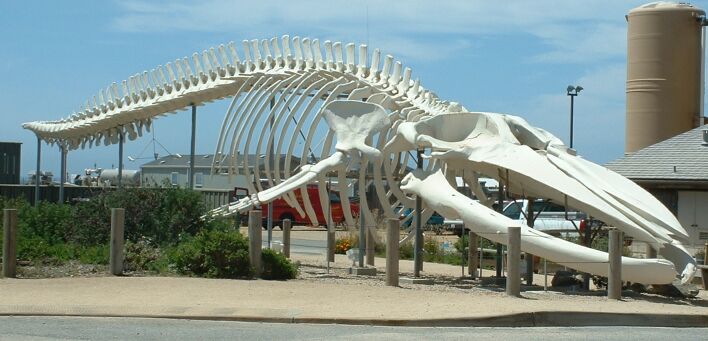
In concert with the above mentioned, next we will use a descriptive screen command tgs (create-tag-strings) we literally need to tag the contour strings to a “tag string” like our ribs are tagged to a spine bone to keep shape.

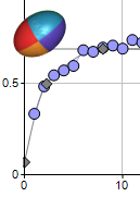
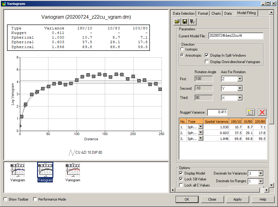
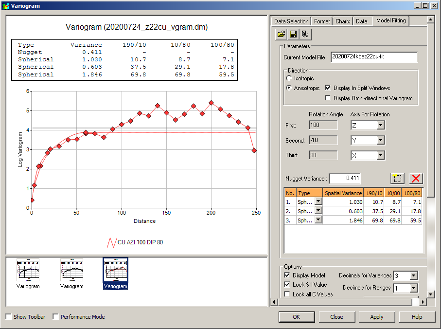
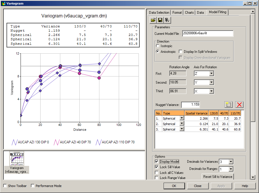
This course is not about variography. A good knowlegde of variogram modelling is an asset. And you, as a mining engineer or a geologist, might not be responsible for calculation and building of variograms. But as a mine modeller, or even as a project manager, you have to have some understanding of what product you are using to contribute to your model.
As I mentioned above, variogram modelling is not mandatory for a mine modeller. Usually, a company keeps a department of "specially trained" but useless talents, which had cost the company hundreds of thousands of dollars on training and international trips, who do variography in 24/7 mode because it is positioned as if variography is a destiny of chosen folks.
I’ve seen dozens of "the chosen chickens” indulged in photo-shopping of variograms to set them up as if made by themselves.
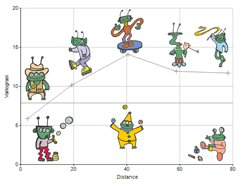
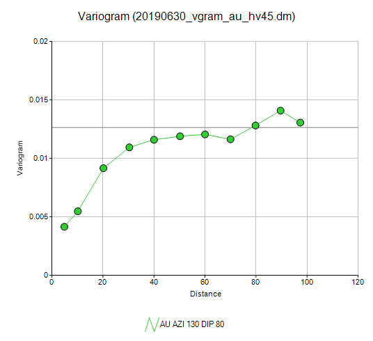
A gold-polymetallic deposit with four domains and six mineral elements. Single directionless and meaningless
                   variogram found in the bankable report made by someone paid as registered geologist.
Many world leading consultants indulge in the variogram photo-shopping business. Beware of them! Some even have no skills to photo-shop and maximum they can do is to swindle innocent clients with “variograms” drawn using Microsoft Office program drawing tools.
If your company farms one of those dedicated folks -- insider or outsider, make sure they do not position themselves as Twelve Olympians (Zeus, Poseidon, Hera, Demeter, Aphrodite, Athena, Artemis, Apollo, Ares, Hephaestus, Hermes, and either Hestia or Dionysus) above your head. Know a few rules how to reprove them:
Incorrect variogram data will lead to waste treated as if ore, or ore dumped as if waste, tons of material not included into mineralization or tonnes of material mistakenly included into mineralization.
If you read this, I hope my words kindled your passion to master geo-statistics!

***
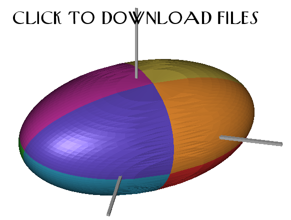
A Link to the Set of Sample Files and Variogram Files with Screenshots and Guides.
***
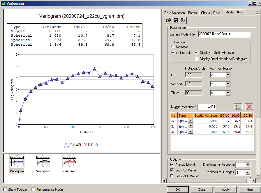
Other Variogram Examples.
scusiani@gmail.com
scusiani@geo-logaritmica.com
+ 995 595 300 121
Anyone interested in variography services, do not hesitate to contact me on:
.png)


***